We offer a 7 day replacement guarantee on all items that arrive defective or damaged. View our full policy here.


All payment methods are fully secure via SSL. We have the following payment methods available: Credit & Cheque Card; Instant EFT; QR Code Apps; Debit Card; MobiCred; and SCode.
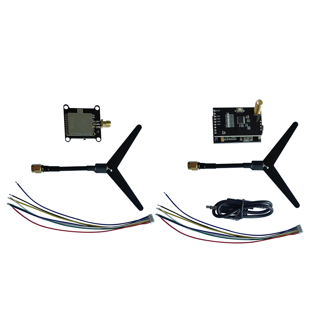
Description
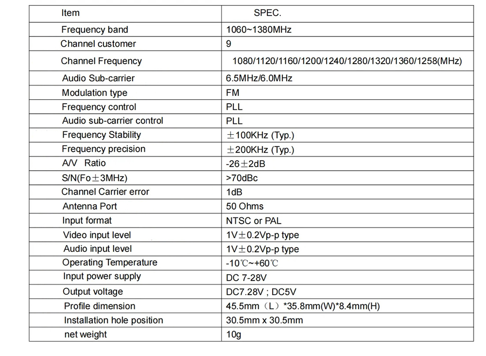
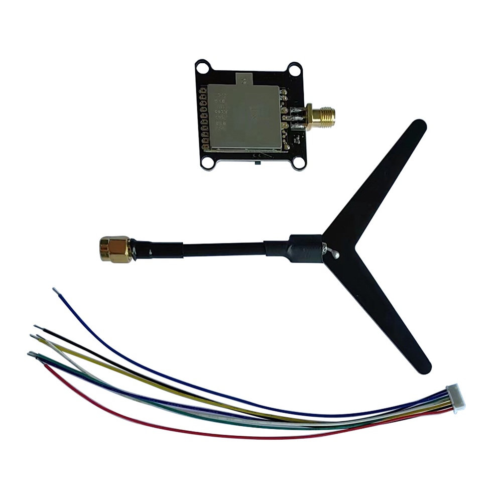
Transmitter:
Button control and LED indicators
Green indicator 4pcs are power indicators: 0.1mW(0)/25mW(D)/200mW(C)/800mW(H).
The default is 0.1mW when the power is on. To the next power level. This operation can be cycled and the corresponding power indicator will light up every time you press and hold the button.The corresponding power indicator will light up each time you press and hold the button.
Note: The transmitting power must be readjusted after each power failure.
The 9 red LEDs are frequency indicators.
This operation can be cycled, each short press on the corresponding frequency point indicator will light up.
Note: The operating system has a memory function, the system will save the current frequency point after power failure.
Interface definition:
The antenna is SMA interface, the antenna head is 'male thread + hole' and the antenna pole is 'female thread + pin'.
Pin' configuration 1.2G special customized 'Y' type antenna.
The order of the socket connection is:
1. power input DC 7-28V;
2. input ground;
3. video input;
4. 6.5M audio input;
5. DC output 7-28V;
6. DC output ground;
7. DC output 5V.
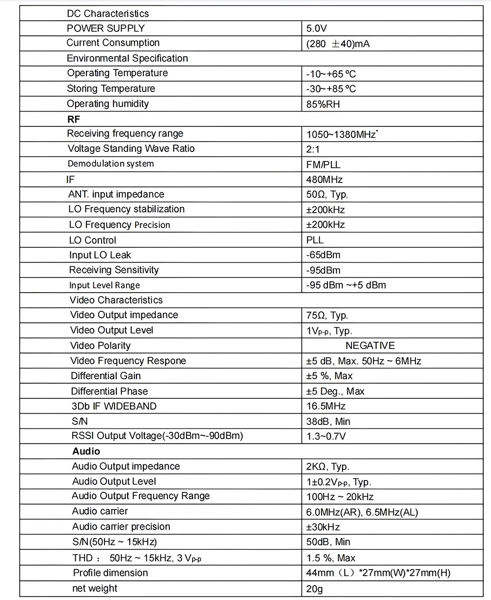
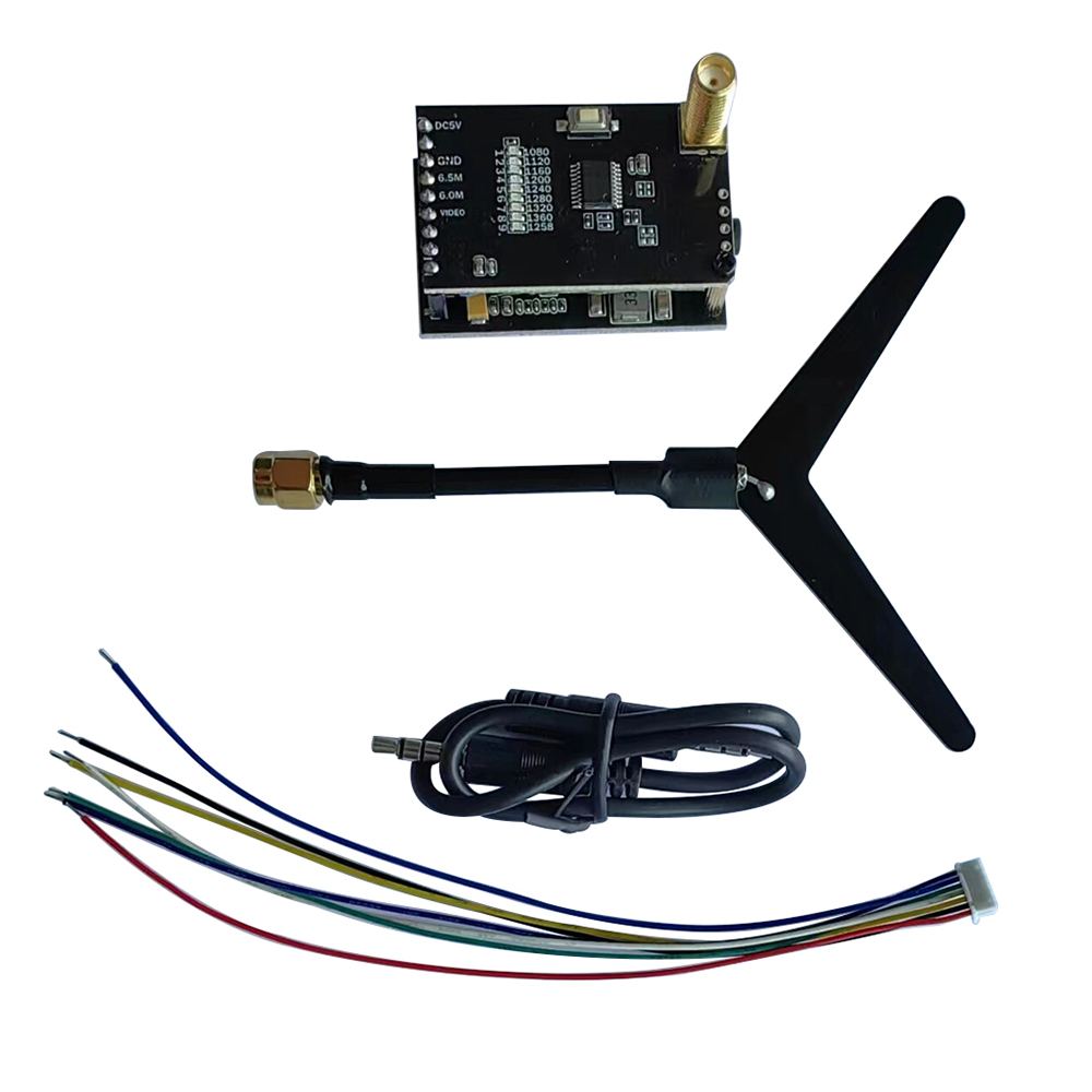
Receiver:
The 9 red indicators are the frequency point indicators and are switched to the next frequency point by pressing the button once.
This operation can be cycled, each short press of the corresponding frequency point indicator will light up.
Note: This operating system has a memory function, the system will save the current frequency point after a power failure.
Interface definition:
The antenna is SMA interface; the antenna head is 'male thread + hole' and the antenna pole is 'female thread + pin'.
Pin' configuration 1.2G special customized 'Y' type antenna.
The order of the socket connections is:
1. power input DC 7-28V;
2. input ground;
3. video input;
4. 6.5M audio input;
5. DC output 7-28V;
6. DC output ground;
7. DC output 5V.
Reserved 5P pads are defined in the following order:
1. power input DC 7-28V;
2. input ground;
3. video input;
4. DC output 5V;
5. DC output ground.